Material Of Construction
- Housing – Cast Iron
- End Plates – cast Iron
- End covers – Cast Iron
- Rotor s – Ductile Iron
- Shafts – Ductile Iron cast integrally with rotor
- Bearings -- Gear End – Double row ball Free end and drive shaft –Single row ball
- Gears – Heat treated & Hardened alloy steel
- Seals – DE & NDE – Double Lip mounted on SS shaft sleeve or Slinger seal, optional-Mechanical Seal, Out board Drive shaft Sea – Double Lip seal or Mechanical Seal
- Lubrication – Oil splash system at both DE & NDE Oil chamber’s with optional water cooling Coils inside the Oil chambers.
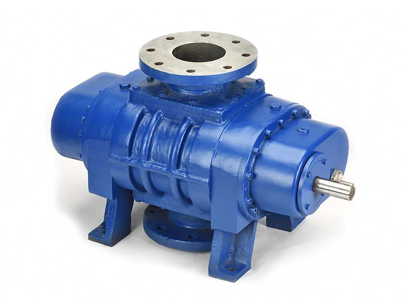
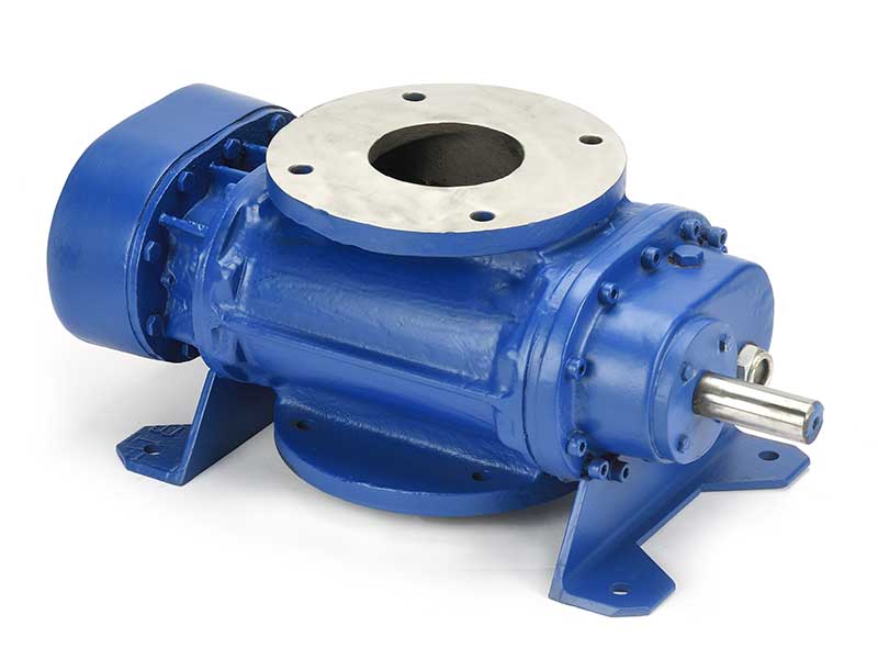
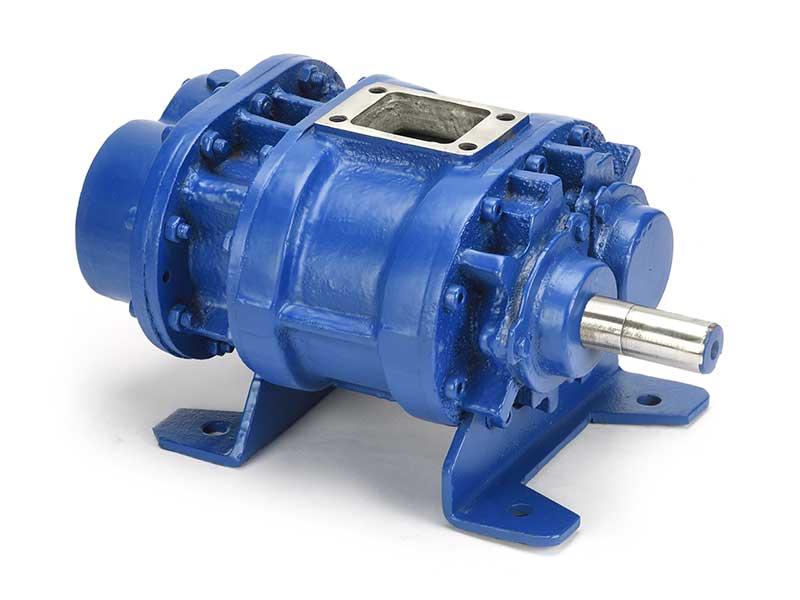
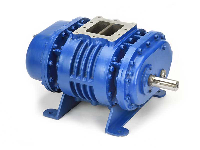
Water/Solvent/Oil Injection Manifold – Fitted inside the square Flange of the Suction Port for uniform water spraying on the end to end length of the Lobes surface Area.
Water Cooled End Plates – DE&NDE – optionally offered.
Standard Construction Coating
- Housing – Cast Iron internally coated with Zylon/PFA/PEEK/PTFE
- End Plates – cast Iron internally coated with Zylon/PFA/PEEK/PTFE
- End covers – Cast Iron
- Rotors – Ductile Iron Externally coated with Zylon/PFA/PEEK/PTFE
- Shafts – Ductile Iron cast integrally with rotor externally coated with Zylon/PFA/PEEK/PTFE
Material Of Construction – SS316 Construction (Optional)
- Housing – SS316
- End Plates – SS316
- End covers – Cast Iron
- Rotors – SS316
- Shafts – SS316
- Bearings- Gear End – Double row ball,Free end and drive shaft –Single row ball
- Gears – Heat treated alloy steel, helical cut
- Seals – DE & NDE – Double Lip seals mounted on SS shaft sleeve Drive shaft – Double Lip seal
- Lubrication – Oil splash system at both DE & NDE Oil chamber’s with water cooling Coils inside the Oil chamber.
Electro Pneumatic Pressure (+Ve)Booster By Pass Valve(Optional)For Cooled Gas Injection At Suction
| Pump Model | MVB250 | MVB400 | MVB600 | MVB900 | MVR1000 | MVR1200 | MVR2000 | MVR2500 | MVR3000 | MVR4000 |
|---|---|---|---|---|---|---|---|---|---|---|
| Type | Butterfly | Butterfly | Butterfly | Butterfly | Butterfly | Butterfly | Butterfly | Butterfly | Butterfly | Butterfly |
| Size | 1” | 1” | 1” | 2” | 2” | 3” | 3” | 3” | 3” | 3” |
| Operation | Manual | Manual | Manual | Manual | Manual | Manual | Manual | Manual | Manual | Manual |
Pressure(+Ve)Booster Suction Vacuum Switch/Transmitter
| Pressure Transmitter | Vacuum Switch |
| Pressure range : 0 to -760mm of Hg abs | Pressure range : 0 to -760mm of Hg abs |
| Differential Pressure :50 mm of Hg abs | Differential Pressure :50 mm of Hg abs |
| Type–FLP/Non FLP | Type–FLP/Non FLP |
| Supply Voltage - 230V/24V,1ph,50Hz | Supply Voltage - 230V/24V,1ph,50Hz |
Pressure (+Ve)Booster Discharge Temperature Switch/Sensor
At discharge of booster pump,temp switch/sensor is provided to cut off the pump at excessive high discharge temp in the event of opening of any valve in system under evacuating leading to atmospheric air inrush etc.
| Temp Sensor | Temp Switch |
| Type : RTD100 | Temperature range : 0 to 150 degC. |
| Gland –FLP/Non FLP | Type–FLP/Non FLP |
| Temperature range : 0 to 150 degC. | Differential Temperature range – 50 degC |
Mechanical Pressure (+Ve) Booster Pump Operation By Variable Frequency Drive (VFD)
The mechanical booster pump RPM is varied w.r.t. the suction pressure from 1000-3000RPM by VFD.This is done through vacuum transmitter o/p signal to variable frequency drive w.r.t suction pressure. The frequency drive operation is programmed as below.
| Pressure transmitter O/P current is proportional to the Inlet pressure | Mechanical Booster Pump RPM setting wrt O/p Current of Pressure Transmitter |
Features Of Operation Of Mechanical Booster Pump By Variable Frequency Drive
- Very fast evacuation from sub atmospheric pressure by Mechanical Booster Pump is possible as the pump rotational speed is controlled by Electronic sensors having fastest response time.
- Mechanical Booster pump can be safe and easily operated at a maximum speed of 2900 RPM , thus pump can be operated at full efficiency as the pump efficiency in terms of suction flow rate and compressibility is highest at high pump RPM. Thus small (reduction in) size of mechanical booster pump.
- Fine control of Pumping capacity to maintain the required pressure & flow in the system under evacuation to prevent carryover of vapours in to the pump or unnecessary overloading of the pump, thus eliminating the need of PID control in distillation unit and energy saving is achieved for required flow & pressure operation of the pumping unit.
- Complete Fail safe and very easy single push button vacuum pumping unit operation. Compact in size and light weight.
| Pump Model | MPB250 | MPB400 | MPB600 | MPB900 | MPB1000 | MPB1200 | MPB2000 | MPB2500 | MPB3000 | MPB4000 |
|---|---|---|---|---|---|---|---|---|---|---|
| VFD Rating(with out Backing Pump) | 10HP | 12.5HP | 20HP | 25HP | 30HP | 40HP | 50HP | 60HP | 75HP | 100HP |
PLC/DCS Based Operation & Control Instrumentation For Mechanical Booster Pump Package
- Pressure Transmitter/Switch at suction of the Booster Pump for measurement & control of Pressure, electrically interlocked to VFD
- Variable Frequency Drive for capacity & pressure control electrically interlocked to Booster Pump Electric Motor
- Temperature Sensor/switch at Discharge of the MVR Pump for measurement & control of Temperature, electrically interlocked to booster pump by pass control Valve
All the Instruments are skid mounted on the Mechanical Booster Pump having common base frame.
Electrical Control Panel
Type – Non Flame ProofAll Electrical Control Circuitry is placed inside the panel for sequential operation of the MVR.It consists of
- Mains Switch – Siemens/L&T or equivalent
- Booster Pump ”ON & OFF” Switches
- VFD is fitted inside the panel
- PLC is Fitted inside the panel
Control Panel is skid mounted on the common base frame of Booster Vacuum Pump with Electrical Instruments Cabling to the Electrical Motor & Instruments.
Interconnecting Piping & Common Base Frame
By pass valve with manifold at suction and is fitted across the booster vacuum pump with interconnecting piping and booster vacuum pump machine along with the Instruments and Electrical Control Panel is Skid mounted on common base frame having easy access to all the equipments for operation and maintenance.
MOC – Common Base frame & Skid – MS Piping – CS/SS| Pump Model | MPB250 | MPB400 | MPB600 | MPB900 | MPB1000 | MPB1200 | MPB2000 | MPB2500 | MPB3000 | MPB4000 |
|---|---|---|---|---|---|---|---|---|---|---|
| FAD at 60Hz at 3600RPM | 272m3/hr | 408m3/hr | 680m3/hr | 918m3/hr | 1224m3/hr | 1360m3/hr | 2040m3/hr | 2720m3/hr | 3400m3/hr | 4590m3/h r |
| FAD at 50Hz at 2880RPM | 225m3/hr | 325m3/hr | 550m3/hr | 750m3/hr | 1000m3/hr | 1100m3/hr | 1650m3/hr | 2200m3/hr | 2750m3/hr | 3700m3/hr |
| Ultimate Vacuum (without backing pump) | <225Torr< 150Torr with Air/water/Solvent/Oil Injection | <225Torr< 150Torr with water/Solvent/Oil Injection | <225Torr< 150Torr with water/Solvent/Oil Injection | <225Torr< 150Torr with water/Solvent/Oil Injection | <225Torr< 150Torr with water/Solvent/Oil Injection | <225Torr< 150Torr with water/Solvent/Oil Injection | <225Torr< 150Torr with water/Solvent/Oil Injection | <225Torr< 150Torr with water/Solvent/Oil Injection | <225Torr< 150Torr with water/Solvent/Oil Injection | <225Torr< 150Torr with water/Solvent/Oil Injection |
| Maximum Pressure Differential across pump (without backing pump) | 800mbar High compressi on ratios in rough vacuum range up to p1/p2 = 5 | 800mbar High compressio n ratios in rough vacuum range up to p1/p2 = 5 | 800mbar High compressio n ratios in rough vacuum range up to p1/p2 = 5 | 800mbar High compressio n ratios in rough vacuum range up to p1/p2 = 5 | 800mbar High compressio n ratios in rough vacuum range up to p1/p2 = 5 | 800mbar High compressio n ratios in rough vacuum range up to p1/p2 = 5 | 800mbar High compressio n ratios in rough vacuum range up to p1/p2 = 5 | 800mbar High compressio n ratios in rough vacuum range up to p1/p2 = 5 | 800mbar High compressi on ratios in rough vacuum range up to p1/p2 = 5 | 800mbar High compress ion ratios in rough vacuum range up to p1/p2 = 5 |
| Discharge Pressure(wi th outBacking Pump) | Atmospheric or above based on suction pressure | Atmospheric or above based on suction pressure | Atmospheric or above based on suction pressure | Atmospheric or above based on suction pressure | Atmospheric or above based on suction pressure | Atmospheric or above based on suction pressure | Atmospheric or above based on suction pressure | Atmospheric or above based on suction pressure | Atmospheric or above based on suction pressure | Atmospheric or above based on suction pressure |
| Maximum Discharge Pressure with suction at Atmospheric Pressure | 1.034barg | 1.034barg | 1.034barg | 1.241barg | 1.034barg | 1.241barg | 1.172barg | 1.034barg | 1.034barg | 1.034barg |
| Electric Motor Power (without backing pump) | 10HP,2pole,3ph,50/60 Hz,440V,28 80/3600RP M | 12.5HP,2pole,3ph,50/60 Hz,440V,288 0/3600RPM | 20HP,2pole,3ph,5 0/60Hz,440 V,2880/3600RPM | 25HP,2pole,3ph,5 0/60Hz,440 V,2880/3600RPM | 30HP,2pole,3ph,5 0/60Hz,440 V,2880/3600RPM | 40HP,2pole,3ph,5 0/60Hz,440 V,2880/3600RPM | 50HP,2pole,3ph,5 0/60Hz,440 V,2880/3600RPM | 60HP,2pole,3ph,5 0/60Hz,440 V,2880/3600RPM | 75HP,2pole,3ph, 50/60Hz,440V,2880/3600RPM | 100HP,2pole,3ph,50/60Hz, 440V,2880/3600RPM |
| Maximum Temperatu re rise Across Pump(With out Backing Pump) | 120degC | 120degC | 120degC | 120degC | 120degC | 120degC | 120degC | 120degC | 120degC | 120degC |
| Recommen dedExhaust Condenser/ silencer for without backing pump | 0.5m2 Shell & Tube | 0.5m2 Shell & Tube | 0.5m2 Shell & Tube | 1m2 Shell & Tube | 1m2 Shell & Tube | 1m2 Shell & Tube | 1.5m2 Shell & Tube | 1.5m2 Shell & Tube | 2.0m2 Shell & Tube | 2.0m2 Shell & Tube |
| Suction & Discharge Port Size | 2” | 2” | 2” | 4” | 4” | 6” | 6” | 6” | 6” | 6” |
| Dimensions (Bareshaft Unit) | 473.3mm(L)X228.6(W)x336.6mm(H) | 524mm(L)X228.6(W)x377.9mm(H) | 625.6mm(L) X228.6(W)x 377.9mm(H) | 703.3mm(L) X304.8(W)x 381mm(H) | 779.5mm(L) X304.8(W)x 381mm(H) | 741.4mm(L) X406.4(W)x 508mm(H) | 830.6mm(L) X406.4(W)x 508mm(H) | 906.5mm(L) X406.4(W)x 508mm(H) | 1008.1mm( L)X406.4(W)x508mm(H) | 1160mm( L)X406.4( W)x508mm(H) |
| Bareshaft Unit weight | 150kg | 170kg | 200Kg | 250kg | 385kg | 530 | 585 | 640 | 720kg | 800kg |
| Noise Level withExhaus t Condenser/silencer | <85dBA | <85dBA | <85dBA | <85dBA | <85dBA | <85dBA | <85dBA | <85dBA | <85dBA | <85dBA |